FIG 1

VersaCap
Owners Manual
Table of Contents
Overview 2
Parts List 3
Layout 4
Installation Instructions 5
Using and maintaining your VersaCap 7
Warranty 9
Tools and Requirements
Overview
Note: There may be some variations between your parts and what is shown, since this manual is standard for all sizes of the VersaCap.
Bedliners - Installations without a bedliner, or an under the rail bedliner would be preferable. These installations leave the bedrail exposed and accessible for the Versacap structure. If your truck is equipped with an over the rail bedliner, be sure it is flat against the top of your bedrail. If it is wavy or twisted you will not get a good seal around the cap.
Stake holes - Many vehicles have the stake holes along the top of the bedrail. You may need to purchase a stake hole cover from your nearest Truck Accessory dealer to get a proper seal in this area.
Complete Parts List
Versacap Model |
91200 |
91300 |
91400 |
91410 |
91500 |
91600 |
91800 |
||
Item# |
Item |
Qty. |
Part # |
Part # |
Part # |
Part # |
Part # |
Part # |
Part # |
| Manufactured Parts | |||||||||
1 |
Cover (each) | 2 |
93200 |
93300 |
93400 |
93410 |
93500 |
93600 |
93800 |
2 |
Rain Channel | 1 |
93201 |
93301 |
93401 |
93411 |
93501 |
93601 |
93801 |
3 |
Post foot | 4 |
93001 |
93001 |
93001 |
93001 |
93001 |
93001 |
93001 |
4 |
Support Post | 4 |
93002 |
93002 |
93002 |
93002 |
93002 |
93002 |
93002 |
5 |
Box Clamp | 4 |
93003 |
93003 |
93003 |
93003 |
93003 |
93003 |
93003 |
6 |
Box liner plate | 4 |
93004 |
93004 |
93004 |
93004 |
93004 |
93004 |
93004 |
7 |
Handle Mechanism | 2 |
93005 |
93005 |
93005 |
93005 |
93005 |
93005 |
93005 |
8 |
Adjustment plate | 4 |
93006 |
93006 |
93006 |
93006 |
93006 |
93006 |
93006 |
9 |
Support bar 1 1/4" | 2 |
93202 |
93202 |
93202 |
93202 |
93202 |
93602 |
93602 |
10 |
Support bar 1 1/2" | 2 |
93203 |
93203 |
93203 |
93203 |
93203 |
93603 |
93603 |
11 |
Short Pivot | 4 |
93204 |
93204 |
93204 |
93204 |
93204 |
93604 |
93604 |
12 |
Long Pivot | 4 |
93205 |
93205 |
93205 |
93205 |
93205 |
93605 |
93605 |
13 |
Channel | 4 |
93206 |
93206 |
93206 |
93206 |
93206 |
93606 |
93606 |
14 |
Bed Extension | 1 |
93209 |
93609 |
|||||
| Hardware | |||||||||
15 |
Lock (1" Cam) | 2 |
94100 |
94100 |
94100 |
94100 |
94100 |
94100 |
94100 |
16 |
Tailgate Lock (set) | 1 |
94105 |
94105 |
94105 |
94105 |
94105 |
94105 |
94105 |
17 |
Rotary Latch Left | 2 |
94110 |
94110 |
94110 |
94110 |
94110 |
94110 |
94110 |
18 |
Rotary Latch Right | 2 |
94115 |
94115 |
94115 |
94115 |
94115 |
94115 |
94115 |
19 |
Pipe for rotary latch | 8 |
94120 |
94120 |
94120 |
94120 |
94120 |
94120 |
94120 |
20 |
Adjustable lock down latch | 4 |
94125 |
94125 |
94125 |
94125 |
94125 |
94125 |
94125 |
21 |
U-Bolt Plate | 4 |
94130 |
94130 |
94130 |
94130 |
94130 |
94130 |
94130 |
22 |
Cotterless Pin 1/2 x 2 3/4 | 6 |
94135 |
94135 |
94135 |
94135 |
94135 |
94135 |
94135 |
23 |
Steel Cable | 15 |
94140 |
94140 |
94140 |
94140 |
94140 |
94140 |
94140 |
24 |
Cable retention washer | 4 |
94145 |
94145 |
94145 |
94145 |
94145 |
94145 |
94145 |
25 |
Nylon Bushing | 4 |
94150 |
94150 |
94150 |
94150 |
94150 |
94150 |
94150 |
26 |
Handle | 2 |
94155 |
94155 |
94155 |
94155 |
94155 |
94155 |
94155 |
27 |
Spring | 4 |
94160 |
94160 |
94160 |
94160 |
94160 |
94160 |
94160 |
28 |
Trim Seal | 26/28' |
94165 |
94165 |
94165 |
94165 |
94165 |
94165 |
94165 |
29 |
Cam Lock sleeve | 2 |
94170 |
94170 |
94170 |
94170 |
94170 |
94170 |
94170 |
30 |
Ball stud for gas spring | 16 |
94175 |
94175 |
94175 |
94175 |
94175 |
94175 |
94175 |
31 |
Connector lock ring | 16 |
94180 |
94180 |
94180 |
94180 |
94180 |
94180 |
94180 |
32 |
Gas spring connector steel | 16 |
94185 |
94185 |
94185 |
94185 |
94185 |
94185 |
94185 |
33 |
Gas spring | 8 |
95XXX |
95XXX |
95XXX |
95XXX |
95XXX |
95XXX |
95XXX |
| Nuts and Bolts | |||||||||
34 |
1/2 x 1/2 Shoulder bolt | 6 |
78180 |
78180 |
78180 |
78180 |
78180 |
78180 |
78180 |
35 |
3/8 Tapping Screw | 10 |
78095 |
78095 |
78095 |
78095 |
78095 |
78095 |
78095 |
36 |
U-Bolt for Rainchannel | 4 |
79042 |
79042 |
79042 |
79042 |
79042 |
79042 |
79042 |
37 |
3/8 x 3" Cap screw | 4 |
71525 |
71525 |
71525 |
71525 |
71525 |
71525 |
71525 |
39 |
3/8 x 2" Hex bolt | 16 |
71515 |
71515 |
71515 |
71515 |
71515 |
71515 |
71515 |
40 |
3/8 x 1" Hex bolt | 16 |
71505 |
71505 |
71505 |
71505 |
71505 |
71505 |
71505 |
41 |
3/8 x 1" Carriage bolt | 12 |
75005 |
75005 |
75005 |
75005 |
75005 |
75005 |
75005 |
42 |
3/8 x 2" Carriage bolt | 4 |
75015 |
75015 |
75015 |
75015 |
75015 |
75015 |
75015 |
43 |
3/8 Flat washer | 28 |
71580 |
71580 |
71580 |
71580 |
71580 |
71580 |
71580 |
44 |
3/8 Lock Washer | 4 |
71585 |
71585 |
71585 |
71585 |
71585 |
71585 |
71585 |
45 |
3/8 Locking nut | 58 |
71595 |
71595 |
71595 |
71595 |
71595 |
71595 |
71595 |
46 |
5/16 x 3/4" Hex bolt | 4 |
71204 |
71204 |
71204 |
71204 |
71204 |
71204 |
71204 |
47 |
5/16 x 1 1/2" Carriage bolt | 8 |
74910 |
74910 |
74910 |
74910 |
74910 |
74910 |
74910 |
48 |
5/16 Locking nut | 24 |
71295 |
71295 |
71295 |
71295 |
71295 |
71295 |
71295 |
49 |
5/16 Lock washer | 16 |
71285 |
71285 |
71285 |
71285 |
71285 |
71285 |
71285 |
50 |
1/2 x 1 1/4" Hex socket screw | 4 |
78462 |
78462 |
78462 |
78462 |
78462 |
78462 |
78462 |
51 |
1/4 x 1/2" Hex bolt | 4 |
71003 |
71003 |
71003 |
71003 |
71003 |
71003 |
71003 |
52 |
1/4 Locking nut | 12 |
71095 |
71095 |
71095 |
71095 |
71095 |
71095 |
71095 |
53 |
#8 x 1/2 self tapping screw | 8 |
78075 |
78075 |
78075 |
78075 |
78075 |
78075 |
78075 |
54 |
#12 x 1/2 self tapping screw | 4 |
78085 |
78085 |
78085 |
78085 |
78085 |
78085 |
78085 |
55 |
Shims for the Rain Channel | 4 |
79056 |
79056 |
79056 |
79056 |
79056 |
79056 |
79056 |
56 |
Super Lube | 1 |
79061 |
79061 |
79061 |
79061 |
79061 |
79061 |
79061 |
57 |
Protective Tape | 1 |
79059 |
79059 |
79059 |
79059 |
79059 |
79059 |
79059 |
Layout
FIG 1

Measurement Table
Description |
Model 200 |
Model 300 |
Model 400 |
Model 410 |
Model 500 |
Model 600 |
Model 800 |
|
| Length | A |
74 1/2" | 80" | 86" | 90 1/2" | 98 1/4" | 80" | 99 3/8" |
| Width | B |
59" | 59" | 59" | 59" | 59" | 67" | 67" |
| Rear Setback | C |
7 9/16" | 8 1/16" | 7 9/16" | 7 9/16" | 8 1/16" | 8 13/16" | 8 13/16" |
| Span | D |
59 3/8" | 59 3/8" | 70 7/8" | 75 3/8" | 77 5/8" | 62 3/8" | 81 3/8" |
| Front Setback | E |
7 9/16" | 12 9/16" | 7 9/16" | 7 9/16" | 12 9/16" | 8 13/16" | 8 13/16" |
Installation Instructions
Caution: Be sure to check under your vehicle before drilling. Do not drill into any lines, wires or gas tank.
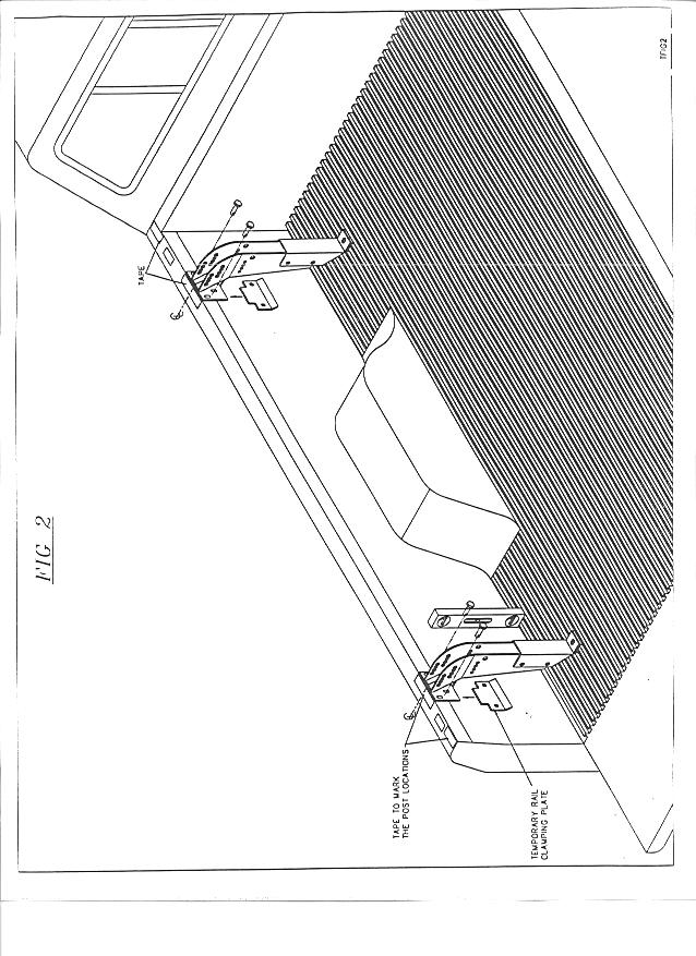
Fasten the post using the 3/8 X 2" carriage bolts. The bedliner spacer is used to raise this bracket off of the ridges of your bedliner. If your truck does not have a bedliner use the bracket underneath the bed as a spacer over the welded seam.(Fig.2)
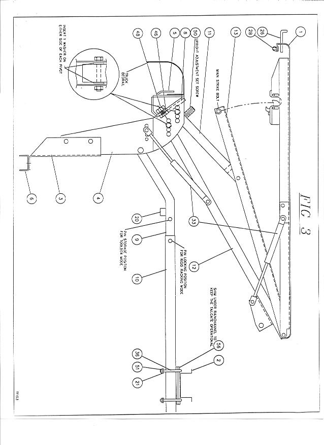
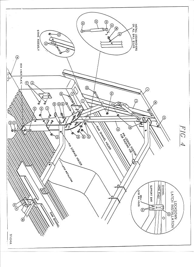
U-bolt on either side once you have located the center. Use the shims provided if you find it necessary to raise the rain channel in order to allow for proper tailgate operation. Once this is accomplished, tighten the U-bolts into place. (Fig.3 & 4)
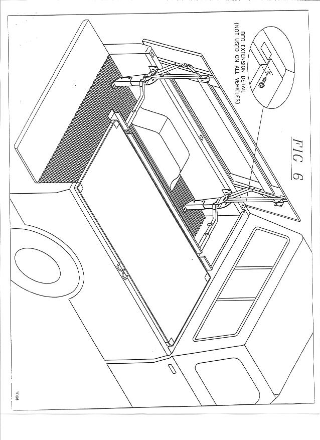
Note: Carefully prop the cover open or have someone hold it while you insert the 3/8 X 2 " bolts through the correct holes to fasten the pivots onto the posts. Be sure to insert the 3/8" flat washers and some grease into the post on either side of the pivots.
Note: Open the cap slowly and carefully, be sure the channel does not contact the outside of your truck box. This can happen if the width adjusting bolts or the adjustment plates are not in the correct position.
The locking pins provided must be used to keep the connectors in place. (Fig.3)
Using and Maintaining your VersaCap
Note: You must always insert the pin into the locking position whenever the support bar is in the racking location.
Installation Notes
